This tutorial is going to teach you how to set up a Raspberry Pi Temperature sensor using GPIO pins and Occidentalis.
So like many others before me I decided to pick up a Raspberry Pi to see what all the fuss is about. Now for those stuck under a rock or if you genuinely don’t know what a Raspberry Pi is, it is basically a small computer slightly bigger than a credit card with a cost of less than $50.
With it’s small size, fairly decent specs and the ability to play HD video the options with the Pi are virtually endless. Add to that the GPIO pins that are attached to the board and it really does open up a whole new world. Already we have seen projects along the lines of home automation, media centres, in-car computers and arcade gaming.
I haven’t had a lot of time to play around or do much development with it but I’ve decided on making a mini weather application. The plan is that around every hour the application will take the current temperature and an image (using a webcam with Motion) before uploading the results to a website (running via a web server on the Raspberry Pi).
Part 1 is going to be all about setting up the Raspberry Pi temperature sensor and reading the data from it.
What you will need
- Raspberry Pi
- Adafruit Pi Cobbler (optional)
- Breadboard (optional)
- DS18B20 temperature sensor
- 4.7k ohm resistor
Raspberry Pi Temperature Sensor
The first step is really setting up the Raspberry Pi itself. This has been done to death in multiple tutorials so I’m not going to go into the details. I’m currently using the Occidentalis v0.2 distro by Adafruit which by default comes with a lot of the packages you will need.
Once this is all setup and you’re happy then it’s time to move on to wiring up the DS18B20 Raspberry Pi temperature sensor. In the parts list I’ve put the Adafruit Pi Cobbler and breadboard as optional but I highly suggest you get them. It makes life a lot easier and can easily save you from doing damage to the Raspberry Pi itself.
It’s very important to get the wire input correct otherwise you run the risk of killing the sensor before you even get it working. The sensor that I’m using (link in the parts list) uses the following. Red = Power, Yellow = Data, Green = Ground. So applying this layout, on the Pi Cobbler/Raspberry Pi we place the Red wire on the 3.3v pin, the Yellow wire on the GPIO #4 pin and the Green wire on the GND pin. The 4.7k resistor goes between the PWR and Data wires (Red and Yellow).
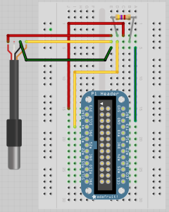
NB: There are two things to note. Firstly, if by the end of this tutorial nothing is working then try placing the Red PWR wire on the 5.5v pin instead of 3.3v. The 3.3v didn’t work for me (and hasn’t for many others) so give this a go. Secondly, if you turn the Pi on and the sensor gets extremely hot (enough to burn you when you touch it) then you have the pin layout wrong and need to double check the wire layout.
Now it’s time to fire up the Raspberry Pi and start reading some temperatures. Once it has booted up you need to firstly use the ‘modprobe’ command to load up the GPIO module in order to read the sensors data. So using ssh or desktop type:
sudo modprobe w1-gpiosudo modprobe w1-thermNext browse to the system devices folder to find the Raspberry Pi temperature sensor device.
cd /sys/bus/w1/deviceslsWhen you issue the listing command under this directory you should see a folder beginning with 28-00000. This is your temperature sensor device. Go into this directory and read out the temperature by issuing the command:
cd 28-00000xxxx # change this to your folder name
cat w1-slaveYou will see an output similar to this:
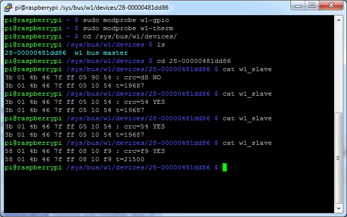
The output will display either YES or NO at the end of the top line. If it is YES, then the temperature is valid and will be at the end of the bottom line. It will show as the temp*1000 so if it looks like a large number just divide it by 1000 to get the correct reading. Eg: 21500/1000 = 21.5C. If it displays NO then re-issue the ‘cat w1-slave’ until you get a correct reading. Putting your fingers over the sensor and issuing the cat command again should show the temperature going up.
Now one annoying part is that each time the Raspberry Pi is restarted you need to re-issue the modprobe commands. A neat little hint I found online will solve this problem. So type this command into a shell terminal and the modprobe commands will be done on startup!
sudo sh -c "echo 'w1_gpio\nw1_therm\n' >> /etc/modules"This is all there is to it. In part 3 of this series I’m going to write a python script which will grab the temperature automatically for you as well as some other neat stuff. Next up though will be getting a webcam and motion working to go side by side with the Raspberry Pi temperature sensor.
Until then feel free to leave a comment or any questions (I’ll do my best to answer) and don’t forget to follow me on twitter!